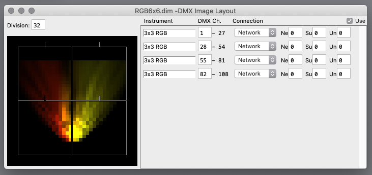

- Clicking a unselected instrument makes it selected.
- Clicking with Shift key expands or shrinks selection, and makes it continuous block.
- Clicking with Control (Windows) / Command (Mac) flips each selection state.
- Dragging/dropping selected instruments moves them.
- Dropping instruments with Control (Windows) / Option (Mac) duplicates them.
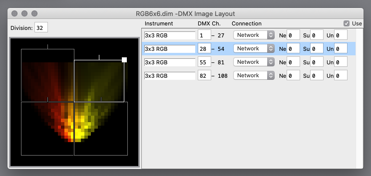
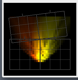
Modifying Instrument Frame
If a mouse cursor is close to a side of Instrument Frame, it will become white, indicating it will respond to mouse.
Clicking/dragging Instrument Frame moves it.
If a mouse cursor is close to a corner of Instrument Frame, it will become white square, indicating it will respond to mouse.
Clicking/dragging a corner of Instrument Frame changes size of it.
If a mouse cursor is close to a Direction Handle of Instrument Frame, it will become white bold segment, indicating it will respond to mouse.
Clicking/dragging a Direction Handle of Instrument Frame rotates it.
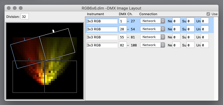
Multiple Instrument Frames can be operated together, as shown above.
(move, size, rotate)
Instrument Settings
- Instrument
An instrument (model) fit into a Instrument Frame.
- DMX Ch,
Start DMX channel of an instrument.
It also indicates channel range occupied by an instrument.
- Connection
Connection to an instrument.
- For "Network", use Art-Net or sACN.
- For Art-Net, specify Ne (Net) , Su (Subnet) , Un (Universe).
- For sACN, specify Un (Universe).
(here it is limited from 1 to 32768, however, sACN itself is defined from 1 to 63999)
- For Art-Net, specify Ne (Net) , Su (Subnet) , Un (Universe).
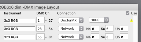
- For "DoctorMX", use our product "DoctorMX" (USB/DMX interface box) and specify a serial number.
Currently, DoctorMX interface box is shipped with unique 4 digit ID programmed.
This ID is immutable regardless USB topology.
Early products has no unique ID, instead 8 digit ID is generated according to USB topology.
It is unique unless USB topology is changed.
We provide a service (at cost) to upgrade early products to recent specification.
For details, see this page.
If a connection cannot be used for any reason (for example, already used by other application), "Warning" is shown.
- For "Network", use Art-Net or sACN.
Changing a selected instrument also changes other selected instruments together.
(excluding DMX Ch.)
Division
Number of division of a long side of source image.
It can be set for convenience for setting operation.
|
If construction scale is pre-determined, it is good idea to set "Division" first, then layout Instrument Frames. "Align" functions (explained later) uses bounds by "Division". There is no need to match display dot of instrument with "Division" for DMX Image to work. However, if "Division" is coarser than display dot, there are adjoining display dots with always same color. |
Use
If this is checked, DMX Image Output works.
DMX Image Menu
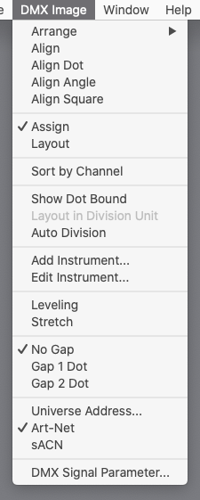
- Arrange
Arranges selected Instrument Frames.
(ignoring rotation)
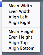
- Mean Width (Mean Height)
Set width (height) of Instrument Frames to mean of them.
- Even Width (Even Height)
Divide evenly between left/right (top/bottom) sides.
- Align Left (Align Right, Align Top, Align Bottom)
Align left (right, top, bottom) sides of Instrument Frames.
- Mean Width (Mean Height)
- Align
Aligns sides of selected Instrument Frames with bounds by "Division".
Size and position of Instrument Frames are adjusted.
Bounds of display dot within Instrument Frame are not necessary to match with bounds by "Division".
(for angled (rotated) Instrument Frame, aligned on its angled coordinate, thus it does not match with bounds on screen)
- Align Dot
Similar to "Align", but display dot becomes same size as unit by "Division".
- Align Angle
Angles selected Instrument Frames to their average angle, then "Align".
- Align Square
Angles selected Instrument Frames to square.
- Assign
Assigns DMX channel (and Art-Net universe, or DoctorMX serial number) in the instrument list.
- Layout
Numerically edit position and size of each Instrument Frame in the instrument list.
[ X ] (horizontal) and [ Y ] (vertical) are position to where the center of an Instrument Frame is placed.
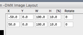
- If [ Layout in Division Unit ] is NOT selected:
Shown and set in percentage.
"0" at center of display area, [-100 100]% corresponds to whole display area for both left/right and bottom/top.
(length of long side is 200%)
(if aspect ratio is not 1, range of short side is narrower)
- If [ Layout in Division Unit ] is selected:
Shown and set in unit derived from [ Division ] and [ Gap ].
"0" at center of display area, and on boundary if even division, or center of division otherwise.
(if aspect ratio is not 1, even/odd of division may also differ between horizontal and vertical)
When [ X ] or [ Y ] is changed, considering a number (even/odd) of dots of assigned instrument, middle dot is aligned to division.
To reduce waste of work, before start layout, first set [ Division ] and [ Gap ], and assign instrument to Instrument Frame.
Use [ Align ] and similar functions as necessary.
- If [ Layout in Division Unit ] is NOT selected:
- Sort by Channel
Sorts instruments in the order of DMX channel (and Art-Net universe, or DoctorMX serial number).
- Show Dot Bound
Shows bounds of display dot within Instrument Frame.
- Auto Division
Set "Division" automatically by Instrument Frames and their instrument specification.
(match to smallest display dot)
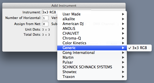
- Add Instrument
Adds display instruments for layout.
Initially, aspect ratio is matched with number of display dot, and multiple instruments are aligned.
Click "Instrument" then select an instrument specification to add.
It assigns required DMX channel and Art-Net universe automatically starting from set in "Assign from".
- Edit Instrument
Create a new, or edit existing instrument specification (explained later).
- Leveling
If selected, source image color corresponding to each display dot is leveled (averaged).
It makes display image smooth.
Otherwise, only a few pixels of source image corresponding to center of display dot are used.
It makes display image sharp.
- Stretch
If selected, source image is stretched to whole display area, ignoring aspect ratio.
Otherwise, Monitor Window defines aspect ratio.
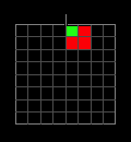
- Gap
Behaves as if there are gap between light points of a device.
This subdivides [Division] and horizontal and vertical points of devices 2 or 3 times.
In each light point of device which is subdivided, only one top-left cell is used.
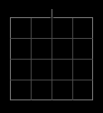
For example below, a device with 4x4 light points.
If [Gap 1 Dot] is selected, for example below, a green cell in a light point is used, and red cells are not used.
(the light point emits green)
- Universe Address
Explicitly specify destination IP address per universe of Art-Net (and sACN).
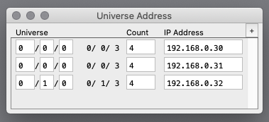
Universe range is specified by "Start universe" and "Number of universes", then "Last universe" is shown for convenience.
If universe is overlapping, upper setting is used.
If IP address is blank or invalid, it is equivalent to unspecified.
If an universe is not specified here,- for Art-Net, broadcast
- for sACN, multicast
- Art-Net、sACN
Specify protocol when "Connection" is "Network".
- DMX Signal Parameter
Some of DMX signal timing can be adjusted.
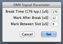
Each setting specifies [ minimum ], and actual average is greater.
Except, [ Mark Between Slots ] of [ 0 ] is actually 0uS.
In other case, on average, about 10uS longer than specified.
Some lighting devices work correctly when [ Mark Between Slots ] is increased.
These settings are saved as preference, and reproduced at next startup.
This feature requires DoctorMX interface box with serial number (ID) 1201 and later.
Earlier interface box needs to be upgraded, and we offer this service (at cost).
For details, seethis page.
This feature is not applicable for ArtNet output.
However, if an ArtNet output is received by DoctorMX, and it uses DoctorMX interface box for final output, Signal Parameters can be adjusted there.
With our product "EtherMX" (Ethernet/DMX node), Signal Parameter can be adjusted.
Instrument Editor
Create or edit display instrument specification.
It is automatically saved at any time it is changed.
(there is no explicit "Save" operation)
Preset instruments cannot be changed.
(however, duplicated one can)
|
User created instrument specifications are saved into a folder "SvDimInstruments" in user's Document folder automatically. Same instrument specifications can be used on other computer by copying this folder. Note that instrument specifications in use are also saved into "Layout File" (explained later) together. Thus instrument specification is not needed to be copied to other computer explicitly for playback purpose. |
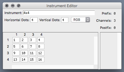
Horizontal Dots, Vertical Dots
Specify number of display dot of an instrument.
Channel assignment of a display dot
Specify channel assignment of a display dot.
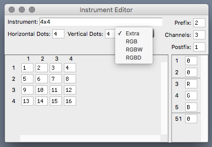
- Extra
Specify number of channels and their function or constant value of a display dot arbitrarily.
Constant value is in range from 0 to 255.
"R", "G" and "B" are used as color components.
"W" is used as "Intensity" (monochrome).
For 16bit value using two channels, set "R", "G", "B" or "W" for both upper and lower channels.
"Prefix" and "Postfix" specify number of channels preceding and following a series of channels that control display dot.
Constant value can be set for these channels.
(if "R", "G", "B" or "W" are specified, it is equivalent to "0")
- RGB
Assigns three channels per display dot.
"R", "G" and "B" are assigned in that order.
- RGBW
Assigns four channels per display dot.
"R", "G" and "B" are assigned in that order, and 4th channel (White) is always "0".
- RGBD
Assigns four channels per display dot.
"R", "G" and "B" are assigned in that order, and 4th channel (Dimmer) is always "255".
Channel order of display dot
Channel order of display dot can be specified.
(this specifies "order" begining from "1", not "channel")
(display dot with order "0" is not used)
Instrument Menu
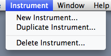
- New Instrument...
Create a new instrument specification.
It begins with naming a new instrument uniquely.
(already existing name cannot be used)
This name is used following selection and identification.
(immutable)
- Duplicate Instrument...
Duplicates an existing (in edit) instrument specification.
It begins with naming a duplicated instrument uniquely.
- Delete Instrument...
Deletes an existing (in edit) user created instrument specification.
DMX Image Layout setting can be saved to and loaded from a file.
On startup, a layout file that is last used is loaded automatically.
Instrument specifications in use are saved into a file together.
Thus they are reproduced when loaded even on other computer.
|
Note that existing instrument specification with same name on running computer takes precedence. |